How to Properly Locate Stack Monitoring Equipment
Posted: July 5th, 2023
Authors: Cheyanne L.
One of the biggest challenges with any continuous monitoring system (CMS) is the collection of representative data. While the technology has been around for decades, it continues to suffer from several issues such as low flow rates, non-laminar flow, sample condensation, loss of polar analytes, system leaks, etc. However, determining the proper sampling location is one way to help ensure the data being collected by a facility is representative of the emissions being generated
Most Continuous Emissions Monitoring Systems (CEMS) extract a sample from a single point within the stack for analysis. Continuous Opacity Monitoring Systems (COMS) measure in situ across the entire stack. Many Continuous Emissions Rate Monitoring Systems (CERMS), such as stack flow monitors, measure at a single point while some technologies measure across the entire stack. Regardless of the type of CMS being used, how do we ensure that the location yields measured values which are representative of what is actually going on within the stack? The U.S. Environmental Protection Agency (U.S. EPA) provides guidelines for installation location of most types of CMS in Performance Specifications (PS) located in 40 CFR Part 60, Appendix B, but are they enough? They could be, depending on certain variables such as the measurement technology, stack gas characteristics, process or combustion conditions, etc.
Measurement location specifications for COMS and CEMS are discussed below and summarized in the following table, along with references to the applicable specification.
Table 1. Summary of Measurement Location Specifications
| Monitoring Equipment |
Reference |
Duct Diameters Downstream of Flow Disturbance | Duct Diameters Upstream of Flow Disturbance |
| COMS | 40 CFR Part 60, Appendix B PS-1 Section 8.1.2 | 4 | 2 |
| CEMS | 40 CFR Part 60, Appendix B PS-2 Section 8.1.2(a) | 2 | 0.5 |
| Stack Flow | 40 CFR Part 60, Appendix B PS-6 Section 1.2 | 2 | 0.5 |
(a)While PS-2 is specific to SO2 and NOX, the definitions are often referenced in other performance specifications.
Exceptions do exist for stacks or ducts where the specifications can’t be met. Additional requirements for these unique stacks or ducts are outlined in the respective citations. If U.S. EPA’s location specifications are followed, the data collected from these CMS have a higher probability of passing initial certification testing and being considered representative. That being said, a review of the measurements within a stack should be considered as well. For your existing CEMS or CERMS, how do your measurements taken during the last Relative Accuracy Test Audit (RATA) using U.S. EPA Reference Methodology at each point within the stack compare with the single measurement collected by the CEMS or CERMS?
Upstream versus Downstream
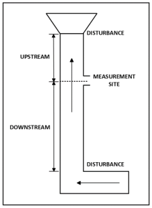
To accurately apply U.S. EPA’s location requirements, the terms upstream and downstream must be understood, and these terms can sometimes be confusing. As seen in Figure 1, upstream and downstream are dependent on the measurement location, the direction of flow, and the location of the nearest disturbance. The terms “upstream” and “downstream” are relative to the location of the disturbance (i.e., the measurement location is downstream from the disturbance at the bottom of the figure but upstream from the disturbance at the top of the figure).
Figure 1. Upstream and Downstream Relative to Stack Measurement Site and Direction of Flow
Opacity
According to PS-1, the opacity measurement location must meet the following requirements:
- Be at least four duct diameters downstream from all particulate control equipment or flow disturbance,
- be at least two duct diameters upstream of a flow disturbance,
- be where condensed water vapor is not present, and
- be accessible to perform maintenance activities.
Other measurement locations and light beam paths may be selected if the facility demonstrates, “to the satisfaction of Administrator or delegated agent, that the average opacity measured at the alternative location or path is equivalent to the opacity as measured at a location meeting the criteria” outlined in Sections 8.1(2)(i) and 8.1(2)(ii) of PS-1.
CEMS
According to PS-2, the CEMS measurement location must meet the following requirements:
- Be at least two equivalent diameters downstream from the nearest control device, the point of pollution generation, or other point at which a change in the pollutant concentration or emissions rate may occur and
- Be at least half an equivalent diameter upstream from the effluent exhaust or control device.
For point CEMS, “it is suggested that the measurement point be (1) no less than 1.0 meter (3.3 ft) from the stack or duct wall or (2) within or centrally located over the centroidal area of the stack or duct cross section.”
For path CEMS, “it is suggested that the effective measurement path (1) be totally within the inner area bounded by a line 1.0 meter (3.3 ft) from the stack or duct wall, or (2) have at least 70 percent of the path within the inner 50 percent of the stack or duct cross-sectional area, or (3) be centrally located over any part of the centroidal area.”
Stack Flow
According to PS-6, the stack flow measurement location must adhere to the requirements specified in PS-2, outlined above. Failure to do so could lead to non-representative mass emissions values.
Summary
The location of stack monitoring equipment plays an essential role in the collection of representative data. U.S. EPA’s placement guidelines will help ensure a facilities compliance with both state and federal emissions limits. ALL4 can help you select a CMS, locate it properly, and evaluate the collected data. If you have any questions regarding a CMS installation or replacement project, please reach out to Cheyanne Laux at claux@all4inc.com for more information.


